DWC Greenhouse Systems

DWC Hydroponic Greenhouse System

10 × 39 m Fixed Vent Solo · Two 4 × 36 m Tanks

A complete deep water culture greenhouse design: two 4 × 36 m insulated tanks holding 86,400 L in a 10 × 39 m greenhouse, with aeration, circulation, UV-C, chilling and automated dosing.

Greenhouse
10 × 39 m
Water Volume
86,400 L
Water Depth
30 cm
Water Temperature
20–22 °C
Download Spec Sheet (PDF)

What It Is

Overview

Deep water culture delivers continuous harvests of lettuce and leafy greens.

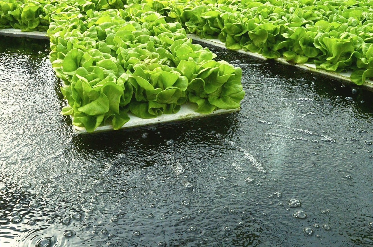
In deep water culture, plants float on rafts over a deep, aerated pool. Two pools of 43,200 L each make the system forgiving: temperature, pH and nutrient levels change slowly, and if the power fails the roots are still in water.

The tanks are built from 75 mm PU/PIR sandwich panels, the panels used for cold-storage rooms, set in galvanised U-channels and staked every 2 m. Unlike concrete, the panels don’t act as a thermal bridge that warms the water, so the chillers run 60% less. They also stay straight over the full 36 m, so rafts never catch on a wavy edge.

Water runs like a slow river. Pumps draw it from the front of each tank through a 130-micron disc filter, UV-C and a chiller holding 20–22 °C, and return it at the back. Seedlings go in at the back, rafts move forward each day, and mature lettuce is harvested at the front.

Installation in five steps: laser-level the floor; anchor the floor track every 1 m; seal and drop in the panels; drive 40 × 40 mm stakes every 2 m; fit the top cap.

Who It Is ForCommercial producers of lettuce, leafy greens and herbs who want a forgiving, continuous-harvest hydroponic system with stable water conditions.

Features

  • A large water volume keeps temperature, pH and nutrient levels stable, and plants stay in water if the power fails.
  • The tanks are built from insulated 75 mm PU/PIR sandwich panels, so chillers run 60% less than with concrete tanks.
  • The panel system cuts installation labour by 70% compared with concrete.
  • Two 1.5 HP regenerative blowers run 24/7, with airlines every 1.2 m.
  • Water circulates front to back at about 15,000 L/h per tank through a 130-micron disc filter, UV-C and a chiller.
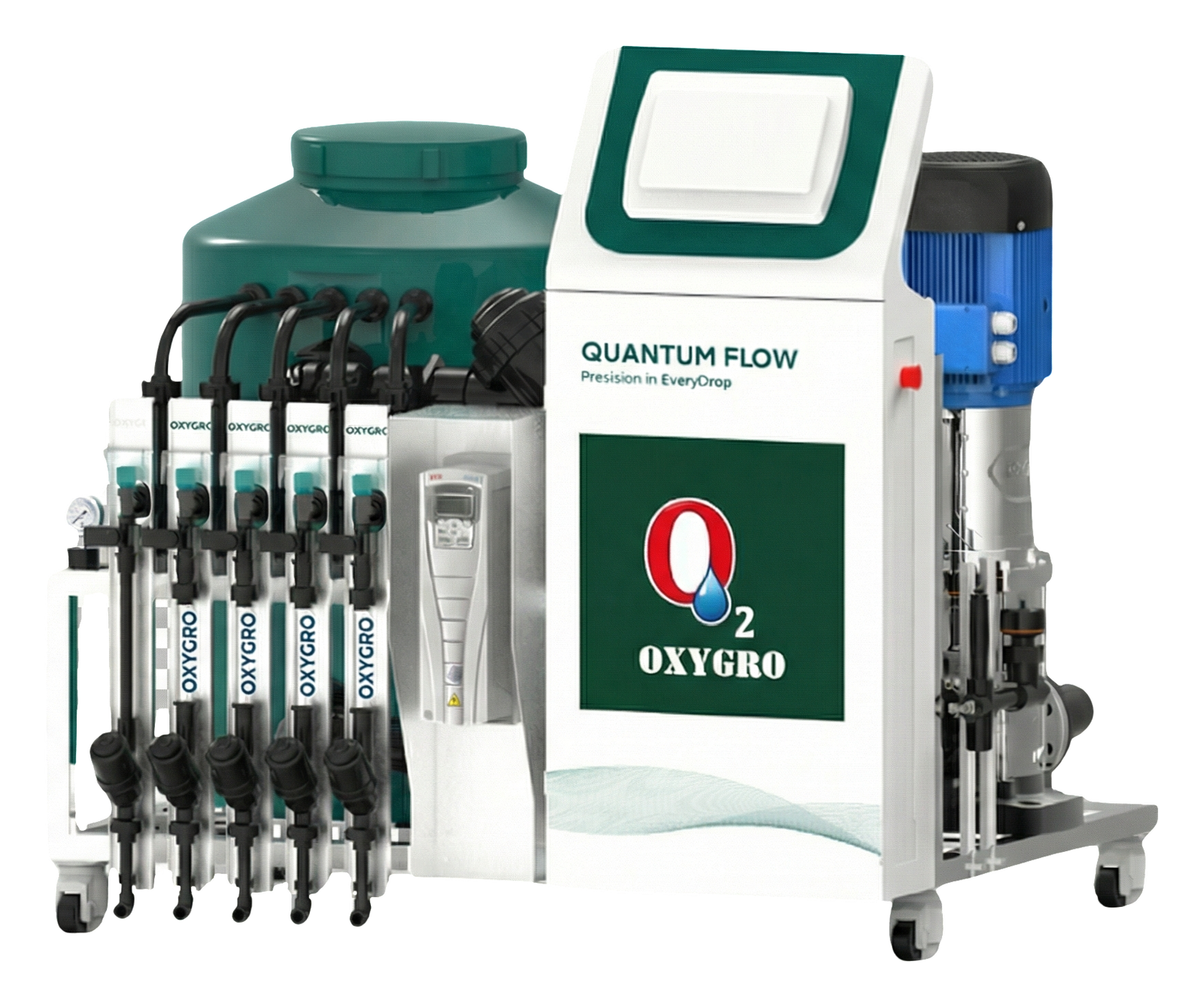
  • An OXYGRO-Inline Quantum Flow unit automates EC/pH dosing.
  • A nano bubble generator dissolves oxygen three times more efficiently.

Specifications

Technical Data

Layout and Water

Layout and Water
ParameterValue
Greenhouse10 × 39 m Fixed Vent Solo
Tanks2 × (4 m × 36 m)
Centre Walkway2 m (harvest carts)
Equipment Space1.5 m at each end
Water Depth / Wall Height30 cm / 40 cm (10 cm freeboard)
Water Volume43,200 L per tank · 86,400 L total

Tank Construction

Tank Construction
ComponentSpecification
Walls75 mm PU/PIR sandwich panel · 0.5 mm steel skins · 400 mm high
Floor Track77 mm galvanised U-channel · 2 mm
Top Cap77 mm galvanised U-channel · 1.5 mm
Floor Insulation50 mm XPS boards
Waterproofing400 gsm geotextile + 1 mm PVC liner
Anti-Bowing Stakes40 × 40 mm galvanised · every 2 m · 600 mm in ground, 400 mm above

Water Management

Water Management
SystemSpecification
Aeration2 × 1.5 HP regenerative blowers (one per tank) · 6 mm airlines every 1.2 m to air stones
Circulation2 × 1.0–1.5 HP centrifugal pumps · about 15,000 L/h per tank · 2-inch (50 mm) PVC
TurnoverEvery 3–4 hours
Filtration130-micron disc filter · washed weekly
DisinfectionInline UV-C · 99.9% pathogen elimination
CoolingCommercial chiller · 20–22 °C (root-disease risk rises sharply above 24 °C)
DosingOXYGRO-Inline Quantum Flow · EC/pH probes · compatible with Bluelab, Hanna and Netafim controllers
Nano Bubble Generator3× more efficient oxygen dissolution · 24-hour oxygen stability

Rafts

Rafts
ParameterValue
MaterialHigh-density XPS
Size1.2 m × 0.6 m × 3 cm
Net-Pot Holes18–28 per raft

Drawings

Layouts and Schematics

DWC greenhouse floor plan, 10 m × 39 m Plan view of the 10 m by 39 m greenhouse. Two tanks, each 4 m by 36 m and holding 43,200 litres, sit either side of a 2 m walkway, with 1.5 m of equipment space at the front and back. In each tank water is drawn out at the front by a circulation pump, sent through the treatment loop and returned at the back, so water and rafts move from the back towards the front, where the lettuce is harvested. Each tank has its own 1.5 HP blower feeding an air pipe on the outer wall with 6 mm airline drops every 1.2 m. 39 m 1.5 m 36 m 1.5 m 10 m 4 m 2 m 4 m Walkway 2 m · harvest carts Tank 1 · 4 m × 36 m · 43,200 L Tank 2 · 4 m × 36 m · 43,200 L Water and rafts: back → front Water and rafts: back → front Out at the front → pump → disc filter → UV-C → chiller → back in at the back Out at the front → pump → disc filter → UV-C → chiller → back in at the back Blower 1 Pump 1 Pump 2 Blower 2 Front end · harvest, water drawn out Back end · seedlings in, water returned Circulation pump, 1.0–1.5 HP, about 15,000 L/h Regenerative blower, 1.5 HP, 24/7 Air pipe on the outer wall, 6 mm airline drop every 1.2 m Equipment positions and pipe routes are schematic.
Fig. 1Floor plan: two 4 × 36 m tanks either side of a 2 m walkway, with 1.5 m equipment zones at each end of the 39 m greenhouse.
DWC tank wall cross-section Section through the tank wall. A 75 mm PU/PIR sandwich panel with 0.5 mm steel skins stands 400 mm high in a 77 mm galvanised floor U-channel, 2 mm thick, and is capped by a 77 mm top U-channel, 1.5 mm thick. A 40 by 40 mm galvanised stake, every 2 m, is driven 600 mm into the ground and stands 400 mm above it, flush against the outside of the panel. Inside, 50 mm XPS insulation covers the floor, then 400 gsm geotextile and a 1 mm PVC liner, which folds over the top cap and is clamped to the outside skin with a flat tension bar. The water is 300 mm deep with 100 mm of freeboard. A 30 mm floating raft carries a net pot with roots hanging into the water, and a 6 mm airline runs from the outside air pipe over the wall to an air stone on the tank floor. 75 mm 400 mm 600 mm 100 mm 300 mm 50 mm Top cap: 77 mm galvanised U-channel, 1.5 mm 6 mm airline over the wall PVC air pipe, outside wall Liner folded over the cap, clamped by a flat tension bar 75 mm PU/PIR sandwich panel, 0.5 mm steel skins, 400 mm high 40 × 40 mm galvanised stake, every 2 m (behind the section) Floor track: 77 mm galvanised U-channel, 2 mm Ground: stake 600 mm below, 400 mm above Seedling in a net pot Floating raft, 30 mm high-density XPS Roots hanging in aerated water Air stone on the floor 1 mm PVC liner 400 gsm geotextile 50 mm XPS floor insulation freeboard water depth Heights to scale. Skins, liner, geotextile and channel thicknesses are exaggerated for clarity. Water depth 300 mm; wall height 400 mm.
Fig. 2Tank wall section: 75 mm PU/PIR panel in galvanised U-channels, staked every 2 m, with XPS floor, geotextile and PVC liner.
DWC treatment loop Each tank has its own loop. Water leaves the front of the tank, passes the circulation pump (about 15,000 L/h), a 130 micron disc filter, an inline UV-C sterilizer and a chiller that holds 20 to 22 °C, and returns at the back of the tank through 2-inch (50 mm) PVC pipe. An automated EC/pH dosing controller injects concentrate into the main pipe as a side branch, guided by EC and pH probes in the tank water. 50 mmPVC Slow “river” flow from back to front Front of tank: water out Back of tank: water back in Circulation pump Disc filter UV-C sterilizer Water chiller 1.0–1.5 HP centrifugal about 15,000 L/h 130 µm washed by hand weekly inline, no chemicals 20–22 °C above 24 °C oxygen drops EC/pH dosing controller dosing pumps + stock concentrate injection into the main pipe EC pH probe signal One loop per tank. Filter → UV-C → chiller; the dosing injection point is schematic.
Fig. 3Treatment loop: pump, 130-micron disc filter, UV-C and chiller, with EC/pH dosing on the main pipe.
Floating raft, 1200 × 600 × 30 mm Plan and side view of a high-density XPS floating raft, 1200 mm by 600 mm and 30 mm thick, with 18 to 28 net-pot holes. The 6 by 4 hole grid shown is an indicative layout. Floating raft · high-density XPS 18–28 net-pot holes Side view 1200 mm 600 mm 30 mm Hole grid is indicative: 18–28 holes per raft.
Fig. 4Raft: 1200 × 600 × 30 mm high-density XPS with 18–28 net-pot holes (hole grid indicative).
Continuous harvest cycle A four-step loop. 1: place seedlings at the back of the tank. 2: rafts float forward daily. 3: harvest mature lettuce from the front. 4: push the remaining rafts forward, then the cycle repeats. Continuous harvest 1234 Seedlings in at the back Rafts float forward daily Harvest at the front Push remaining rafts forward Rafts with young seedlings are placed at the back of the tank. The slow back-to-front “river” current carries the rafts along the tank. Mature lettuce is harvested from the front every day. The remaining rafts are pushed forward, making room at the back.
Fig. 5Continuous harvest: seedlings go in at the back, rafts move forward daily, and the crop is harvested at the front.

Applications

Where It Is Used

3 Crops · 3 Products

Lettuce, Leafy Greens and Herbs

Deep water culture gives continuous, daily harvests of lettuce, leafy greens and herbs from stable, aerated, chilled water.

Works With
Related Products

Fertigation

OXYGRO-Inline

OXYGRO-Inline delivers high-flow fertigation with a 500 L mixing tank and optional drain-water reuse.
Pump Flow
30–65 m³/h
Dosing Channels
Up to 11
Mixing Tank
500 L
Water Treatment

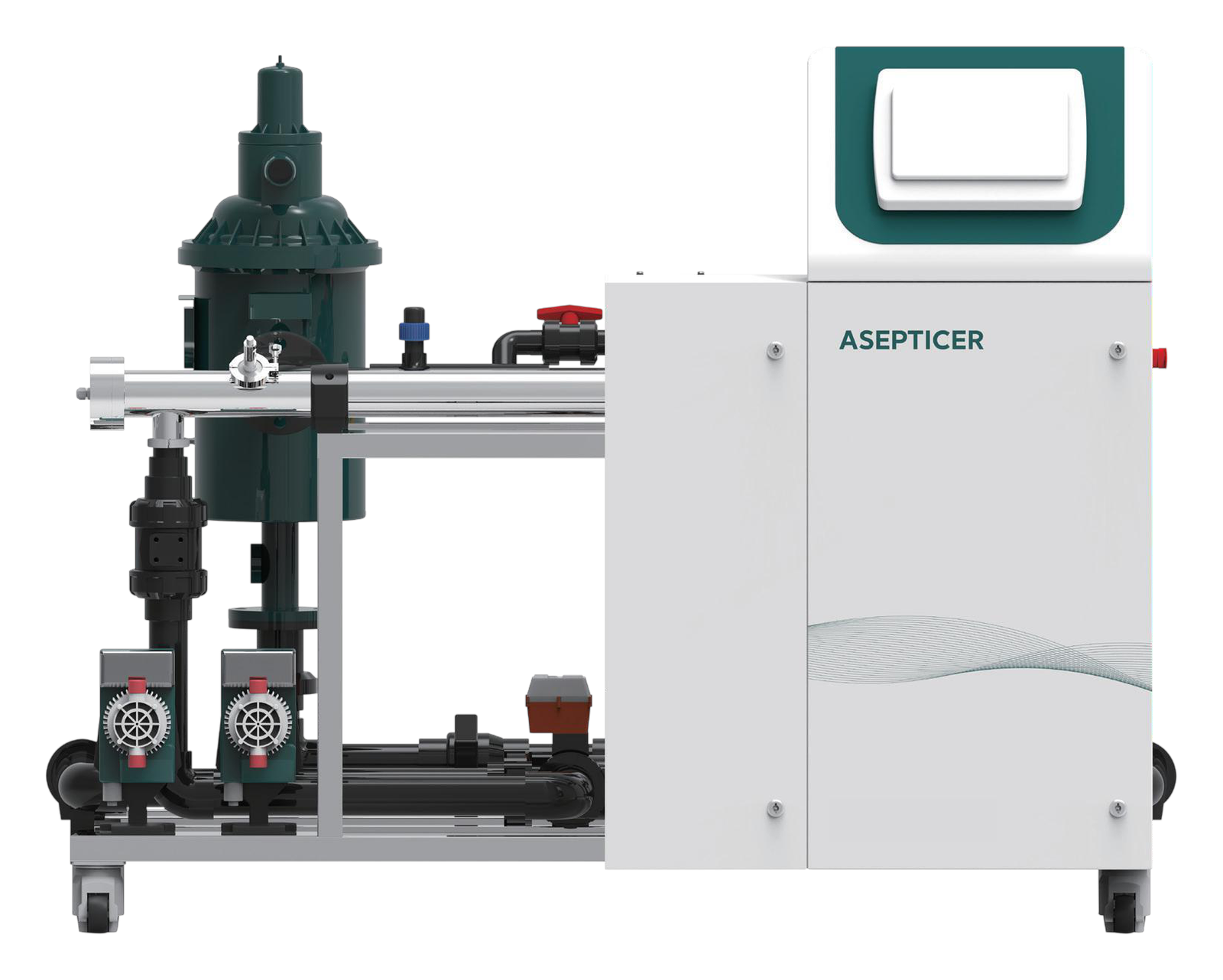
ASEPTICER UV Disinfection Machine

The ASEPTICER disinfects drain water with medium-high-pressure UV so it can be reused.
UV Lamp
1000 W
Lamp Life
18,000 h
Capacity
5–40 m³/h
Fertigation

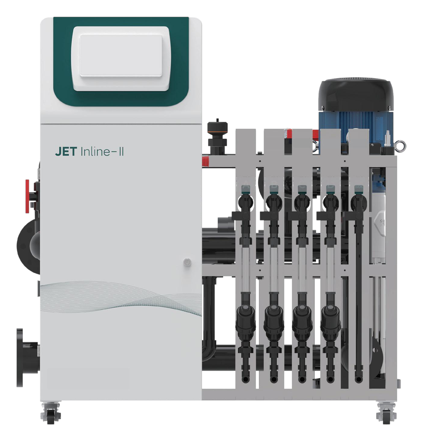
JET Inline-II and JET Inline-III

JET Inline doses fertiliser on the mainline for soilless crops.

Irrigation Flow
15 / 32 m³/h
Fertiliser Channels
5
Inlet / Outlet
DN50 / DN80

Get a Quote for the DWC Hydroponic Greenhouse System

Tell us your crop, flow rate and number of irrigation zones and we will confirm the model, edition and options.

Request a Quote
WhatsApp